- [email protected]
- +91 90421-96988 / +91 95974-49221
- Enquiry
HEAT EXCHANGER & PRESSURE VESSEL DESIGN
HEAT EXCHANGER & PRESSURE VESSEL DESIGN
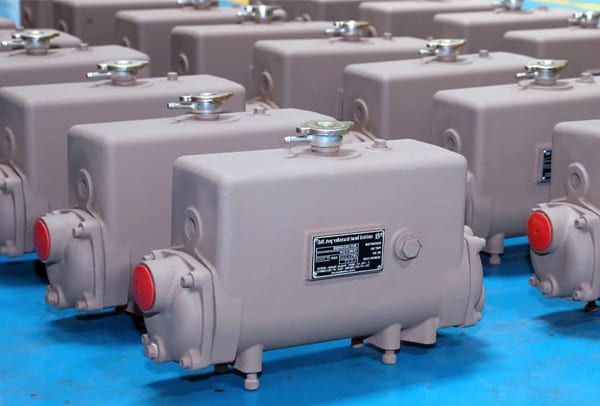
Design of Thermal energy:
- Process fluids are taken into account on both the shell and tube sides.
- Choosing the Necessary Temperature Ranges,
- Reducing the pressure drop on the shell and tube side,
- Determining Velocity Limits for Shell and Tube Sides,
- Using the proper correlations, get the heat exchanger’s overall heat transfer coefficient.
- Determining the Fouling Factor and Heat Transfer Area.
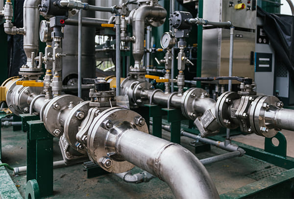
Design of Mechanical Systems
- TEMA Layout Selection: Based on Thermal Design
- Tube parameter selection: material, pitch, thickness, size, and layout
- Using Tube Length to Limit the Upper and Lower Designs
- Material baffle cut, baffle spacing, and clearances are the parameters that are chosen for the shell side.
- The substance of the tubes’ thermal conductivity.
- Establishing upper and lower design limits for baffle cut, baffle spacing, and shell diameter.
The approximate overall design criteria serve as the basis for the material selection.
- Part A of ASME Sec II: For Ferrous Materials
- Part B of ASME Sec II: For Non-Ferrous Materials
- ASME Sec II, Part C: For Filler Metals, Electrodes, and Welding Rods
- ASME Sec II-Part D: For Material Properties
The mechanical design is finished based on the data and materials chosen.
For pressure vessels and U-stamp vessels, ASME Sec VIII Div 1 Boiler and power piping ASME Sec I. (S stamp vessels) For the repair and modification of pressure vessels (R stamp vessels), NBIC Parts 1, 2, and 3
- Thickness of Shell
- Thickness of Dish
- Selection of Flanges in accordance with B 16.47 and B 16.50 (A and B Serious)
- Pipe and nozzle selection in accordance with ASME B 36.10 M
- Pipe and socket fittings in accordance with ASME B 16.11 M
The HTE Design Team will finish the design portion with a production drawing by adhering to the Quality Control Manual (QCM). following the Authorized Inspector’s approval of the design calculations and drawings.
The U stamping process will be used to begin production. If the buyer requests it, the vessel should be registered with the National Board. We will do so and add a “NB” stamp to the name plate along with the serial number of the vessel.
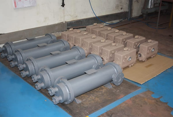
When making vessels according to the production drawing
Below are the Acceptance Norms:
- ASME Sec IX:Qualification Standard for Blazers, Welders, and Welding and Brazing Operators
- Non-Destructive Examination (ASME Sec V)
- Acceptable Procedures and Tolerances in Production (ASME Sec VIII Div 1)

We adhere to our Quality Control Manual for the following Design and Construction for
- Air-cooled Heat Exchangers Design, in addition to the Shell and Tube Heat Exchanger Design
- Design of Double-pipe Heat Exchangers
- The Design of Finned Tube Heat Exchangers
- The Design of Plate-Finned Heat Exchangers
- Condenser Design
- Design of Air-cooled Condensation System
- Types of Heat Exchangers for Kettle Reboilers
- Design of U Tube Bundle Heat Exchangers
- Design of a Pressure Vessel
- Design of Ship Parts
- Design of Repair and Alteration Work
- Design of Heat Recovery Systems
Along with NB registration, different kinds of custom heating and cooling solutions for every industry are designed, manufactured, and tested using the U, S, or R stamps. Heat Transfer Equipments Pvt Ltd’s facility can produce highly precise results even for scenarios involving structural design.
